TheHomeInspectorsNetwork.org
Information and Support for the Professional Inspector
Most home inspection standards require inspectors to inspect and report on grounding and bonding. This information is intended to be a basic explanation of how home inspectors can make this determination during their (visual) inspection.
There are two definitions that must be understood when dealing with the principle of grounding. An “effective grounded-fault current path” is defined as an intentionally designed electrically conductive path capable of handling a high amount of current, intended to carry current in a ground fault situation, from the source of the ground fault on the wiring system back to the source of the electrical supply and facilitate the proper operation of overcurrent protection devices of ground fault detectors. A “ground-fault current path” is an electrically conductive path from the source of the ground fault on the wiring system through normally non-current carrying conductors, equipment or the earth back to the source of the electrical supply. To simplify, these are both an emergency path that current takes in the event of a ground fault (a short from a hot conductor to ground). The main difference between these two pathways is that the effective grounded-fault current path is intentionally designed for this purpose, where the ground-fault current path encompasses any path that the current may accidentally flow through (such as a metal gas line).
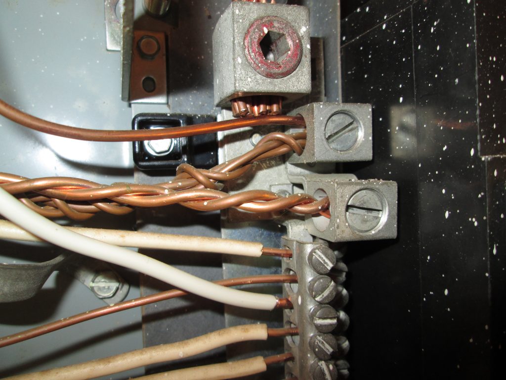
The “grounding electrode system” is made up of the “grounding electrode conductor” and the wires and connections that allow for an effective grounded-fault current path. The electrode is the material that provides contact with the earth. The two most typical ones in use today are the concrete encased electrode (typically a length of re-bar installed through the slab during construction) and the driven ground rod. There are specific rules governing the length (8’ minimum) and measuring a resistance of 25 ohms or less. To eliminate the process of determining a grounding electrode’s resistance in the field, the code was changed to require two rod electrodes. Be aware that there are always going to be exceptions to specific codes (in this case, one grounding electrode will suffice if the measured resistance is 25 ohms or less), and the local code official (AHJ) always has the last word on enforcement. There are multiple code requirements dictating the protection and installation of the GEC, most of which are beyond the scope of the typical visual home inspection. The one requirement that is easily observed is that the GEC wire should be installed in one continuous length, without splices or joints, which create possible failure points. Again, there are some specific code requirements which provide exceptions to this rule, so be careful making any definitive statements regarding splices in the GEC wire.
Be safe out there!
Please Share with Friends!